|
|
Contents Introduction Lightscape System Specter System Radiance System Scenes for Comparison Experimental Results Conclusion Acknowledgments |
|
A.B. Khodulev, E.A. Kopylov
|
|
Contents Introduction Lightscape System Specter System Radiance System Scenes for Comparison Experimental Results Conclusion Acknowledgments |
|
The most exhaustive comparison was done for the "theoretical" scene CUBE. We executed several runs of all the systems requesting luminance values at specified points. Then we calculated actual errors for each system. We used Power Indigo 2 computer. The results are discussed in sec. 5.1.
The comparison for the ROOM scene (images and luminance values at 3 characteristic points are compared) is described in sec. 5.2. A visual comparison of images (in color fringes) for the CUBE scene is discussed there as well.
Finally, we generated images for complex scenes. They are briefly commented in sec. 5.3.
Starting from the conclusion, LVS has shown very distractive results from the viewpoint of accuracy. They are summarized in the table 3. We present results of 3 LVS runs differing by subdivision control parameters (the only way to control simulation accuracy in Lightscape). "Subdivision range" column gives minimum and maximum sizes of subdivided mesh (in meters; size of cube edge is 10 m). We used luminance values in points A (the center of a face, the most accurate result) and point F (a face corner, the least accuracy). The average (for the whole face) luminance is also included (discussed below). Lightscape reports this average automatically. The theoretical value for the average luminance of a face is 666.7 nit. This value can be easily obtained by pure theory, without reference to any simulation.
| subdiv. range (m) |
time (min) |
luminance at points (nit) | rel. error at points | ||||
| A | F | Average | A | F | Average | ||
| 1 - 1 | 0.5 | 585 | 116.5 | 490 | -34.4% | -70.0% | -26.5% |
| 1 - 1 | 14 | 843 | 206 | 590 | -5.5% | -46.9% | -11.5% |
| 0.3 - 1 | 20 | 846 | 199 | 595 | -5.2% | -48.7% | -10.7% |
| 0.01 - 1 | 40 | 847 | 191 | 595 | -5.1% | -50.8% | -10.7% |
Table 3. Lightscape results for the CUBE scene.
Note: the results in the first line are obtained by interruption of LVS simulation after 30 seconds of work.
We see that LVS results are rather inaccurate. Even for the average value LVS systematically gives underestimate by more than 10%. Thus, we can deduce for sure that Lightscape looses energy when doing global illumination analysis. Investigation of other columns of the table shows that the greatest losses (luminance underestimate by about 50%) are near the cube corners. Moreover, increasing granularity of subdivision doesn't improve accuracy considerably; and the value at point F even goes in the opposite direction becoming farther of theoretical values for finer meshes.
The results are summarized in table 4. The 3 points were used for the comparison: A (the center of a face, the most "simple" point); D (the center of an edge, "intermediate difficulty") and F (a face corner, the most "difficult" point, the least accurate results). We executed several Specter runs for different parameters. We varied subdivision of cube face and requested accuracy of Specter simulation. Face subdivision determines how accurate the "ideal i-map" can be - the piece-wise linear luminance distribution which Specter results approach as time passes. Subdivision denoted as, say, 10x10 means that each face is subdivided into grid of 10x10 = 100 squares each subdivided into 2 triangles that totals in 100*2*6 = 1200 triangles for the whole cube.
The actual Specter results are some (unbiased) approximation to the ideal i-map values. Due to probabilistic nature of the Specter simulation method the values obtained are not repeated in a series of runs with the same parameters which causes some difficulties in calculating the errors (errors are random too and in a single run we can get very accurate results by coincidence). To provide more accurate error estimation we averaged errors for several Specter runs with the same parameters. Quadratic mean was used. In the table below these averaged errors are presented (and actual results are not included as they vary).
| subdivision | accuracy requested |
time (min) |
rel. error at points | ||
| A | D | F | |||
| 10 x 10 | 8% | 0.15 | 2.0% | 8.4% | 20.7% |
| 4% | 0.5 | 2.6% | 5.7% | 11.6% | |
| 2% | 1.7 | 1.0% | 6.5% | 16.2% | |
| 1% | 8 | 0.8% | 4.3% | 15.8% | |
| 20 x 20 | 16% | 0.2 | 7.4% | 16.8% | 48.8% |
| 8% | 0.5 | 4.5% | 4.5% | 23.1% | |
| 4% | 1.8 | 3.4% | 5.3% | 18.1% | |
| 2% | 7.4 | 0.4% | 4.0% | 10.1% | |
| 1% | 31 | 0.7% | 3.0% | 10.5% | |
| 40 x 40 | 16% | 0.7 | 10.9% | 31.6% | 46.4% |
| 8% | 2.5 | 8.8% | 14.6% | 17.5% | |
| 4% | 10 | 1.4% | 5.4% | 13.3% | |
| 2% | 39 | 1.0% | 3.7% | 7.9% | |
| 1% | 156 | 0.3% | 1.5% | 8.8% | |
Table 4. Specter average errors.
Next the RADIANCE results are presented. There are a lot of options controlling accuracy of RADIANCE simulation. We call RADIANCE (rtrace utility) with the following options:
-dt 0 -lw 0 -lr 12 -ad 1024
and set different numbers of "ambient bounces" (-ab option), ranging from 1 to 10 (it is analog of radiosity iterations). The results are presented in the following table.
| bounces | time (min) |
luminance at points (nit) | rel. error at points | ||||
| A | D | F | A | D | F | ||
| 1 | 0.02 | 591.5 | 277.6 | 160.7 | -33.7% | -50.8% | -58.6% |
| 2 | 0.7 | 694.0 | 370.8 | 225.9 | -22.2% | -34.3% | -41.8% |
| 3 | 2.8 | 771.0 | 453.7 | 286.4 | -13.6% | -19.7% | -26.2% |
| 4 | 4.2 | 820.5 | 502.7 | 330.6 | -8.0% | -11.0% | -14.8% |
| 5 | 4.9 | 850.1 | 533.8 | 355.8 | -4.7% | -5.5% | -8.3% |
| 6 | 5.0 | 868.1 | 550.4 | 369.1 | -2.7% | -2.5% | -4.9% |
| 7 | 5.1 | 879.0 | 561.7 | 381.0 | -1.5% | -0.6% | -1.8% |
| 8 | 5.1 | 885.4 | 561.2 | 385.0 | -0.8% | -0.6% | -0.8% |
| 9 | 5.2 | 889.1 | 571.6 | 388.3 | -0.4% | 1.1% | -0.02% |
| 10 | 5.2 | 891.2 | 566.8 | 391.9 | -0.2% | 0.3% | 0.9% |
Table 5. Radiance results and errors.
To compare the systems from the viewpoint of the accuracy / time criterion we should use results produced in comparable time. We can choose the best possible results for a given time. Let's take the second line of LVS table (time = 14 min), as time increase doesn't lead to better accuracy; the last line of the Radiance (5.2 min) and Specter results for 20x20 subdivision and 2% requested accuracy (7.4 min). Comparison definitely shows that the accuracy of LVS results is under acceptable level; Specter provides reasonably accurate results (the worst error about 10% in the most difficult point F) while the Radiance results are even more accurate.
|
|
|
Fig. 2 (a) CUBE. Point A. 800x600, 12K |
Fig. 2 (a) CUBE. Point F. 800x600, 11K |
Fig. 2a, 2b contain graphs of accuracy for all the three systems in dependence on computing time. Graphs for points A and F are drawn based on data in the above tables. (In case of Specter we vary several parameters controlling accuracy. As a result we have not a monotonous dependency of accuracy on time. For example, as is clear from table 4, the Specter results for the subdivision 40x40 and requested accuracy 16% are beaten by the results for subdivision 20x20 and the requested accuracy 8%. We excluded such evidently worse points from the Specter graphs.)
The graphs evidently confirm the above conclusion about relative accuracy of the systems.
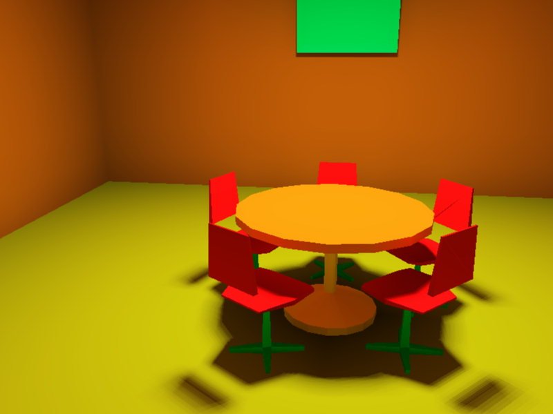
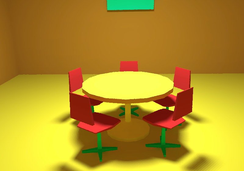
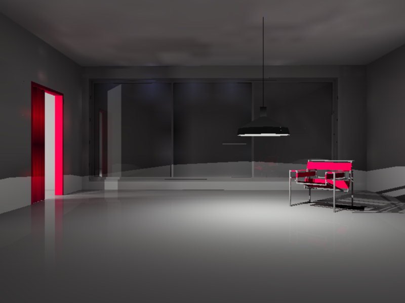
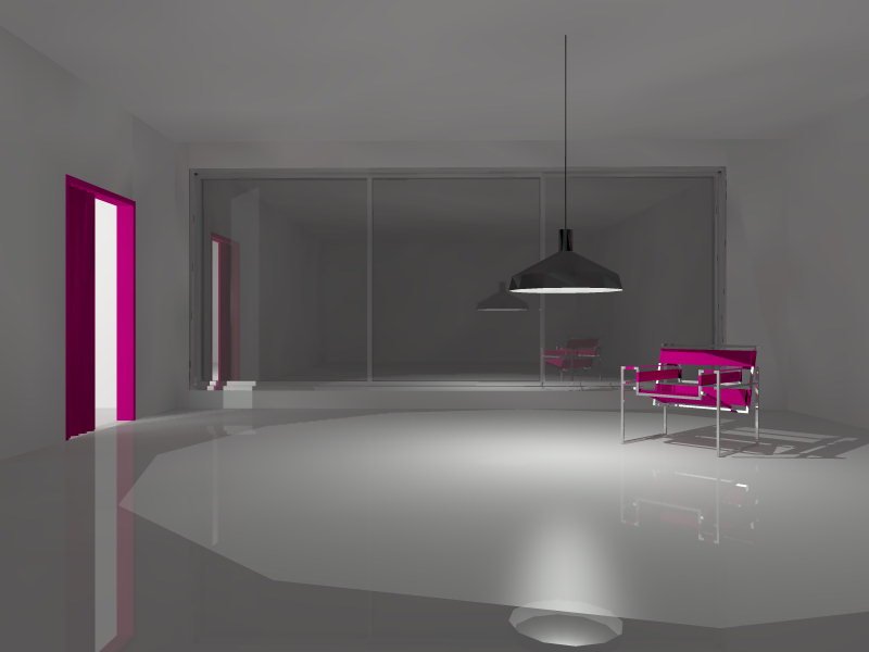
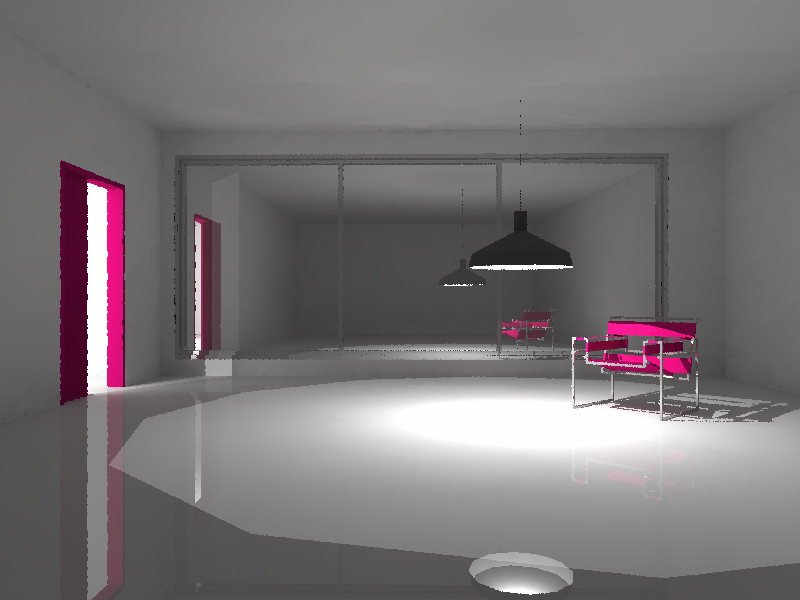
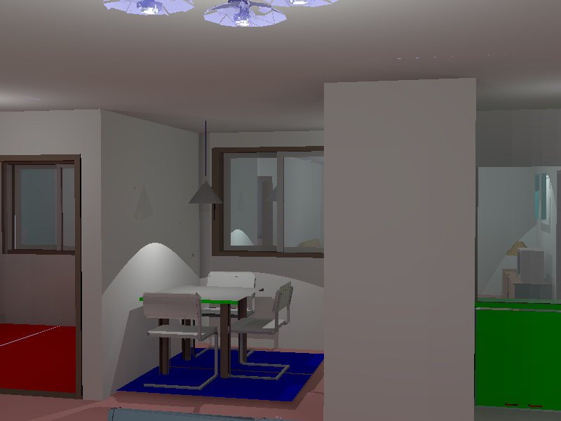
As was mentioned in sec. 4, we used the scene ROOM for visual comparison of image quality. We generated images by all 3 systems working for comparable time (Fig. 3); time values are included in table 6 below.
|
|
|
|
(a) LVS (800x600 31K) |
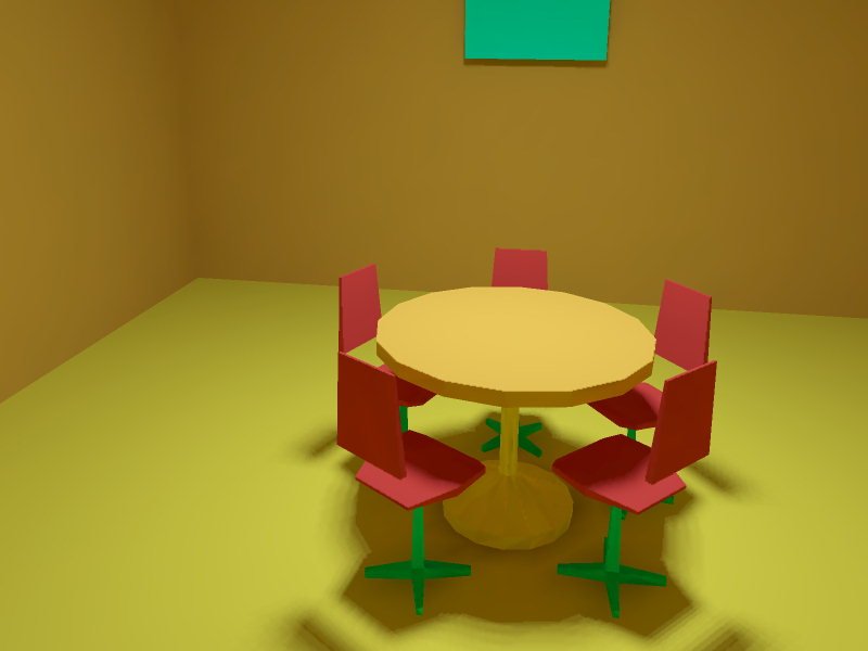
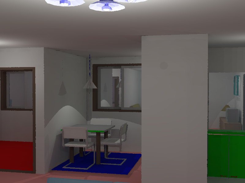
(b) SPECTER (800x600 27K) |
(c) RADIANCE (800x600 32K) |
Fig.3. ROOM.
(the model courtesy of Lightscape Technologies,
Inc.)
Looking at the images we see that all images look satisfactorily, as human might expect, though they are different in color and contrast. These differences can be most probably explained by differences in schemes of conversion from physical luminance units to RGB triples sent to display. Radiance applies a simple "gamma-correction" model for this conversion. Specter uses a more complicated scheme based on Stevens formula [MNM84]. LVS did not reveal the information about scheme of RGB generation it uses; however looking at the image (LVS image has the greatest contrast among all) one can guess that a simple linear mapping (corresponding to gamma=1) is used by LVS.
More thorough investigation of the images discovers some slight flaws in each of them. LVS image has some strange black line at one chair. A reason is unknown (probably a bug in system). Specter image exhibits random noise (non-smoothness) in shadow areas with small details (under table). This effect is inherent to the Monte Carlo simulation; we discuss it later. Radiance image shows sharp borders (not very contrast but clearly distinguishable) in some places (e.g. table leg) while there should not be them. A reason is unclear, but this effect depends in some random way on "-ds" parameter controlling light source sampling. Also all images exhibit not smooth shadow of chairs, especially noticeable in right-near chair. This is caused by an extended source sampling procedure (extended source is treated as a collection of point ones) that works analogously in all systems.
We also tried to estimate accuracy of simulation for this scene. To do so we need to solve two problems. The first is, of course, absence of reference theoretical data. So, instead of absolute accuracy estimate we applied simple "majority rule": we compare results for the three systems and if it happens that any two of them give close results while results of the third system are more distant from the first two ones (as it actually occurred) then we can deduce (with some certainty) that the first two systems are more accurate than the third one. Moreover, a distance between the first two results is a reasonable upper bound for the error of them both, while accuracy of the third system can be estimated by distance of its results from any of the first two ones (or, for symmetry, from the average of them).
For this comparison we choose 3 points in the scene: point A is the middle of the table top desk (mostly direct illumination); point B lies on the floor in the middle between two nearest chairs in shadow (only indirect illumination); point C is the far left corner of the floor (direct + indirect illumination, difficult for simulation due to wall closeness). Luminance at all these points was extracted for all the 3 systems.
At this point we encountered another (unexpected) problem: all the 3 systems use different approaches to convert 3-channel RGB luminances to integral (physical) luminance value. Radiance sums three R,G,B components with the weights, respectively, 0.3, 0.589, 0.111. LVS uses other coefficients (we determined them experimentally, as user manual did not contain necessary information), they are: 0.263, 0.655, 0.082. Specter simply uses equal weights for R,G,B components. So, it is unreasonable to compare directly luminance values produced by different systems. (This problem does not influence comparisons for CUBE as only white colors are used there and for white light all the three schemes are equivalent.)
Fortunately, Radiance and Specter provide capability for obtaining the three color components of luminance separately (as opposed to LVS that reports only integral luminance). So, to get comparable data we take these three components and combine them in integral value using LVS weights. These values are included in table 6; we remind once more, that they are not the direct results of Specter and Radiance, but the results processed in accordance with the LVS color summation scheme.
| LVS | Specter | Radiance | |
| simulation + rendering time (min) |
125 | 95 | 87 |
| luminance at points (nit) | |||
| A | 986.8 | 946.9 | 935.8 |
| B | 30.6 | 70.5 | 70.2 |
| C | 96.6 | 142.5 | 148.0 |
| rel.error at points | |||
| A | 4.8% | <1.2% | <1.2% |
| B | 56.5% | <0.4% | <0.4% |
| C | 33.5% | <3.8% | <3.8% |
Table 6. Accuracy analysis for the ROOM scene.
We can see (from "Luminance" rows) that for all points the Radiance and Specter results are much closer to each other than the LVS results are to both of them. So, in accordance with the above reasoning we take average of Specter and Radiance results as reference data to estimate accuracy of LVS, while accuracy of Specter and Radiance is estimated (as upper limit) by difference of their results.
Based on these results we can not distinguish which of Specter and Radiance is more accurate in this scene, we can conclude only that LVS is noticeably less accurate than each of the two others. This conclusion is in agreement with the comparison based on the simple scene CUBE.
Let's return to visual quality of images. Carefully investigating the Specter ROOM image we can notice slight unsmoothness of the image. It has random character and is more noticeable at small geometrical elements located at shadow (the base of the table and the chair legs). It is characteristic feature of Monte Carlo algorithms. This noise reduces with increase of simulation time. Backward Monte Carlo ray tracing used in Radiance is better suited for generation of smooth images (than Specter Forward Monte Carlo ray tracing), so this random noise is apparently not noticeable in the Radiance ROOM image.
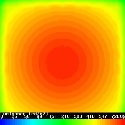
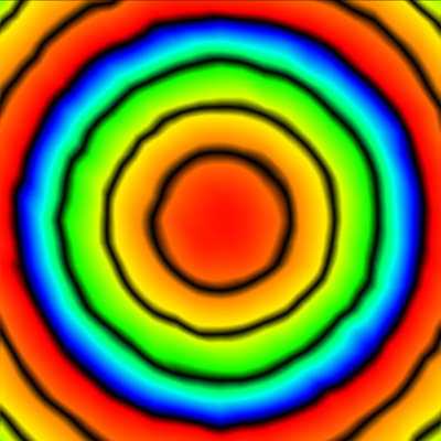
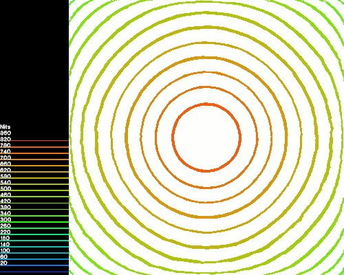
To show the random noise inherent to the Monte Carlo solutions more explicitly, we use CUBE images. While ordinary images of CUBE face look as smooth gray-scale diffuse spots without any details (maximum brightness at the center), we can use the color fringe technique to reveal small deviations and non-smoothness of luminance. In this technique different colors are assigned to different luminance levels; as human eye is much more sensitive to color variations than to change of brightness, the color fringes are a very sensitive tool for qualitative analysis of luminance distribution.
We prepared images in color fringes for each system (Fig. 4). When comparing them it should be taken into account that each system uses a different scheme of color fringe assignment. Each image presents look of one cube face. Lines of equal luminance (equal color) should look as approximate circles. It is so in the LVS CUBE image (Fig. 4a) with the exception of some proximity of face boundary where image become unclear (no lines are visible). As we could expect basing on the numerical analysis, the LVS results in proximity of boundary are very imprecise.
|

|
|
(a) LVS 400x400, 19K |
(b) SPECTER (subd. 40x40, acc. 1%) 400x400, 33K |
|
|
|
(c) SPECTER (subd. 20x20, acc. 1%) 400x400, 18K |
(d) RADIANCE 500x400, 59K |
Fig. 4. Color fringes for CUBE image.
Let's look now at the Specter image (Fig. 4b) corresponding to the most accurate simulation (the last line of table 4). In spite of the fact that the results are much more accurate than that of LVS, the image looks worse because of noticeable random noise. It illustrates the fact that image smoothness is not necessary connected with accuracy. By performing a more accurate (and more time consuming) simulation in Specter we can reduce this noise. Look at the Specter image in Fig. 4c (subdivision 20x20, accuracy requested 0.5%). It looks much more smooth. Nevertheless, accuracy of this result is worse than of the previous one (due to more crude subdivision).
Finally, the Radiance image (Fig. 4d) also exhibits some random noise, but smaller than that of Specter.
Images for complex scenes are presented in Fig. 5-9. Simulation time spent by each system is shown in table 7. It should be mentioned that in most cases we had to interrupt LVS simulation (after several days of run) when an image visually stops changing. LVS failed to do lighting simulation for the largest scene HONSHA (caused system error).
| name | Simulation + rendering time (hours) | ||
| LVS | Specter | Radiance | |
| APART2 | 86 | 0.3 | 3.7 |
| DREAM0 | 5.4 | 2.3 | 4.3 |
| FLOWER | 34 | 1.3 | 0.7 |
| CG | 27 | 4.1 | 31 |
| HONSHA | ? | 29 | 38 |
Table 7. Processing time for complex scenes.
Looking at the images we can see some general features:
Below are some additional comments to particular images.
|
|
|
|
(a) LVS (800x600 29K) |
(b) SPECTER (800x600 28K) |
(c) RADIANCE (800x600 38K) |
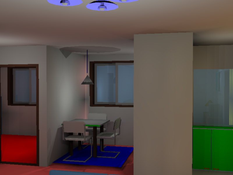
Fig.5. APART2.
(the model courtesy of Integra, Inc.)
Some random noise is noticeable (at the ceiling) in the images generated by all the 3 systems. The level of this noise is the smallest in the Radiance images, intermediate in the Specter image and the biggest in the LVS image. Appearance of "random" noise in the LVS image is strange as it does not use probabilistic algorithms.
An additional flaw of the LVS image - seemingly incorrect reflection (the door is reflected in the floor with gradual attenuation; the lamp is not reflected in the floor; chair is not reflected in the window). A probable reason is that both the reflected surfaces in this scene combine specular and diffuse reflectivity and the local reflection model that LVS applies for such surfaces is really strange (and not properly documented in user manual) so that we don't know how to convert such surfaces to LVS. The attribute settings used in this scene were found after several experiments; and as we see they are still not perfect.
|
|
|
|
(a) LVS (800x600 32K) |
(b) SPECTER (800x600 36K) |
(c) RADIANCE (800x600 36K) |
Fig.6. DREAM0.
(the model courtesy of KOREA NATIONAL HOUSING
Corp.)
The images by Specter and Radiance are close but each one has its own drawbacks. Radiance generates an artifact in the form of a darker spot at the upper part of the middle column. It is analogous to sharp borders observed in the scene ROOM. The reason is unclear. Specter generates some artificial bright lines. Also one segment of the leg of the closest chair is absent in the Specter image. The reason is probably the same in both cases: dirty geometry (very thin triangles or coplanar overlapping triangles). It is known that Specter is sensitive for such flaws of input geometry.
The LVS image is considerably different. It contains some bleeding of rose color at the far left corner. The reason is unclear. Also a shadow of cone light fixture on the ceiling and the walls is quite different. There are two reasons for this. Firstly, the LVS scene is really different. In the Specter and Radiance scenes the light source is spotlight, it emits light inside of cone angle. So, the shadow border is due to boundary of the light emission, it is not a shadow of light fixture. In LVS there is no cone light, so we used ordinary point light that emits light in all directions.
Nevertheless, even when we try to use point light in Specter, the shape of the shadow is different. The reason is that the light source in LVS is placed differently compared with Specter and Radiance. This becomes clear if we observe the shadow cast by closest chain on left wall. It goes very close to the lower corner in LVS scene and at a noticeable distance of it in Specter and Radiance. It looks as if the light source in LVS is located lower than in Specter or Radiance. This is a bug in LVS. Initially we put the light source in the correct position, but when light simulation is started in LVS, the position of the light source is changed. We observed the same behavior in a simple test scene and did not find any way to bypass this bug.
|

|
|
|
(a) LVS (800x600 36K) |
(b) SPECTER (800x600 34K) |
(c) RADIANCE (800x600 35K) |
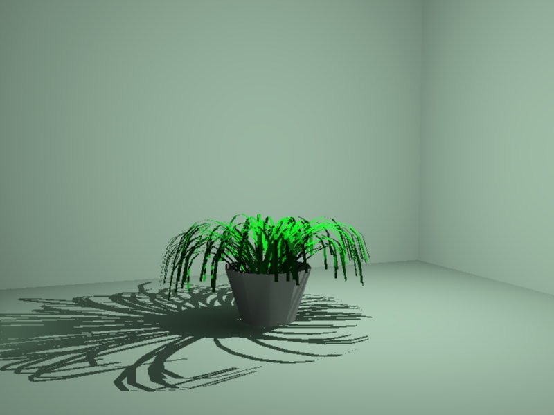
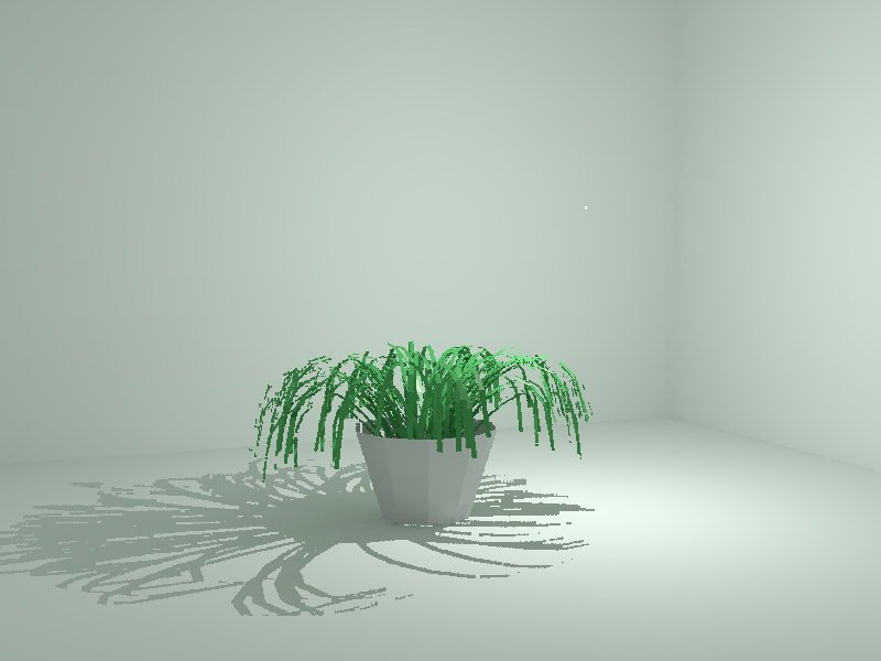
Fig.7. FLOWER.
(the model courtesy of Voxel Visual Computing,
Ltd.)
No special remarks. Due to rendering quality Radiance image of the plant itself is noticeably worse (jaggy and even broken in some places) than Specter one.
|
|
|
|
(a) LVS (800x600 35K) |
(b) SPECTER (800x600 33K) |
(c) RADIANCE (800x600 38K) |
Fig.8. CG.
(the model courtesy of Matsushita Electric
Works, Ltd.)
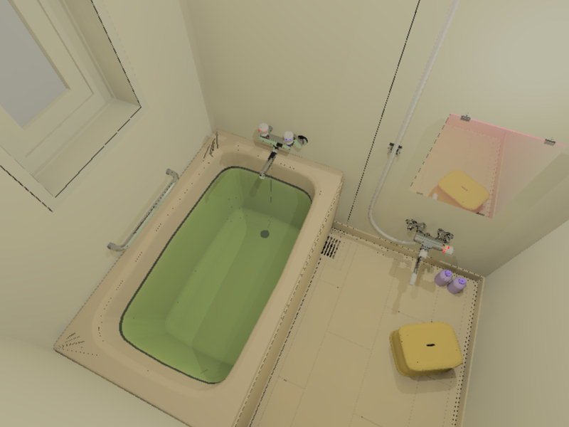
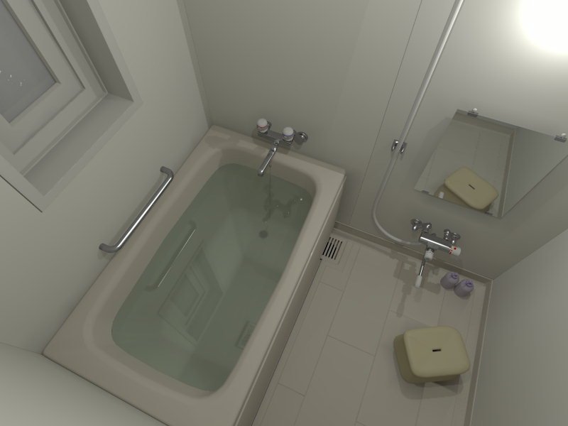
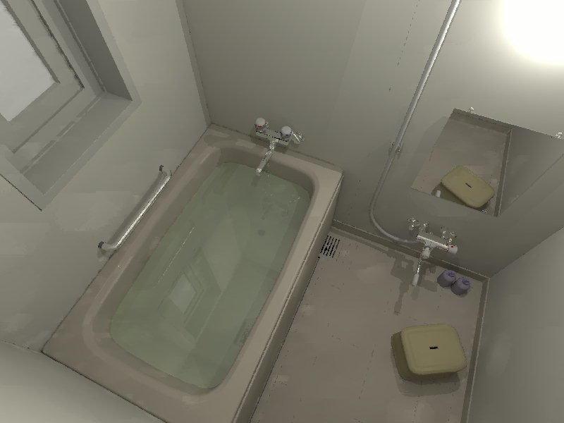
LVS image is the worst of the three:
(1) Some inconvenient features of geometry (like long thin triangles) injure LVS (a dark "web" at the corners of the bath; a dark band at the water boundary). Geometry-sensitive Specter survived this time.
(2) The mirror, having in the original Specter scene slightly blue color and small diffuseness becomes light pink in LVS image. This is the result of the same difficulty mentioned in APART2 discussion: without information about the local reflectance model in LVS the problem of attribute conversion Specter->LVS becomes non-trivial. Maybe this effect can be avoided. An analogous problem was encountered for metallic parts. Here we experimentally tuned attributes for a metal surface to provide the most natural view; but naturality of metal reproduction in LVS is still inferior compared with the two other systems.
The Radiance image exhibits a small but noticeable random noise (mainly on the floor) while the Specter images are free of it in spite of the fact that Specter calculated this image an order of magnitude faster than Radiance.

|
|
|
|
(a) LVS (no image) |
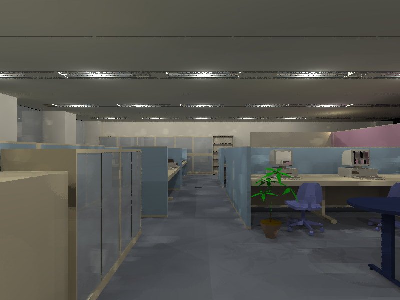
(b) SPECTER (800x600 39K) |
(c) RADIANCE (800x600 48K) |
Fig.9. HONSHA.
(the model courtesy of Hibiya Engineering,
Ltd.)
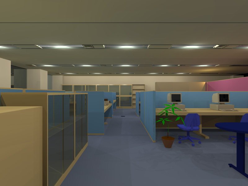
This is the most complex of all the tested scenes. LVS failed to do lighting simulation for this scene. Radiance image now has a rather high level of random noise, so that the picture looks "noisy", as opposed to Specter with smooth image. Look of display screens seems suspicious in the Radiance image, actually the screens have a very dark color so we can expect that they will look dark (as in Specter image).
It seems that in Radiance, to produce good image for complex scenes, user should increase values of some control parameters. These parameters are specified in different terms like number of rays, level of jittering, etc. The situation is quite different in Specter where the main accuracy-control parameter is specified as the relative average level of random deviation in scene illuminance distribution (in percent).
|
|
Contents Introduction Lightscape System Specter System Radiance System Scenes for Comparison Experimental Results Conclusion Acknowledgments |
|
|
|
|
| © Copyright 1996 Andrei B. Khodulev, Edward A. Kopylov.- All Rights Reserved | [Home] |