Preliminary experimental results of a facility to test hysteresis rod parameters: effect
of the magnetic field of a permanent magnet
|
|
Composition |
Initial magnetic permeability
|
Maximum magnetic permeanility
|
Coercitive Field
|
Saturation
flux density
|
Saturation Field
|
Elongation of rod-2
|
|
79%
Ni, 17% Fe, 4% Mo |
60000 |
164000 |
0.96 |
0.74 |
12 |
46 |
Table 2. Main values of different configurations for test
on the hysteresis rod-2
|
|
|
|
|
|
0.5 |
3.73 |
37.30 |
|
|
1.0 |
7.46 |
74.63 |
|
|
2.0 |
14.90 |
149.25 |
|
|
18.3 |
136.6 |
1366 |
|
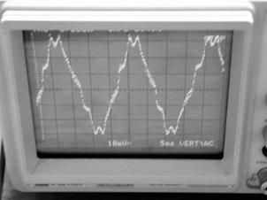
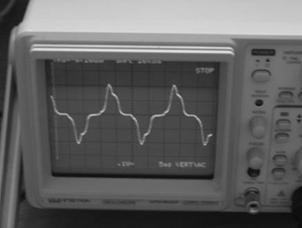
Fig. 2. Results of the tests on the hysteresis rod-2:
(left) signal for Vcoil=0.5V; (right) signal obtained for Vcoil=18.33 V
Test in a metallic box showed that these irregularities do not depend by
noise and we have a hypothesis about their dependence by characteristics of the
rod related to technological heat treatment and manufacturing process. Also in
the second case measurements have been replicated in different configurations
changing inclination of coil-1 with respect to the Earth magnetic field. Its
direction has been established with a compass. Measurements have been obtained
for a random inclination (Series-I random ![]() ), in the perpendicular direction of coil-1 with respect to
the Earth magnetic field direction (Series-II perpendicular
), in the perpendicular direction of coil-1 with respect to
the Earth magnetic field direction (Series-II perpendicular ![]() ) and in the same direction of Earth magnetic field (Series
III-parallel
) and in the same direction of Earth magnetic field (Series
III-parallel ![]() ). Results are collected in Fig.3, Fig.4 and Fig.5
respectively for
). Results are collected in Fig.3, Fig.4 and Fig.5
respectively for ![]() . In these diagrams one can see the trend of magnetic field
inside of rod-2: X axis represents the length of hysteresis rod, Y axis
represents experimentally values obtained during tests in laboratory along the
rod-2 for induced voltage in coil-2. Diagram shows three sets of measurements
with different positions of the facility with respect to the Earth magnetic
field direction.
. In these diagrams one can see the trend of magnetic field
inside of rod-2: X axis represents the length of hysteresis rod, Y axis
represents experimentally values obtained during tests in laboratory along the
rod-2 for induced voltage in coil-2. Diagram shows three sets of measurements
with different positions of the facility with respect to the Earth magnetic
field direction.
Fig. 3. Three sets of measurements with different
positions of the facility with respect to the Earth magnetic field direction.
Results for rod-2, Vcoil=0.5 V.
Fig. 4. Thee sets of measurements with different
positions of the facility with respect to the Earth magnetic field direction.
Results for rod-2 when Vcoil=1V.
Fig. 5. Three sets of measurements with different
positions of the facility with respect to the Earth magnetic field direction.
Results for rod-2 when Vcoil=18.3V.
In the centre of the rod one can see that signal has an amplitude which
is in several times bigger than signal in the extremities of rods. A comparison
with results obtained for rod-1 shows that when ![]() the amplitude of
signal for the two rods is about the same changing from 20 mV in the
extremities until 100-120 mV in the centre of the rod. Rod-1 and rod-2 show the
same trend when voltage applied to coil-1 changes with some differences related
to the amplitude of the signal measured with the coil-2. When
the amplitude of
signal for the two rods is about the same changing from 20 mV in the
extremities until 100-120 mV in the centre of the rod. Rod-1 and rod-2 show the
same trend when voltage applied to coil-1 changes with some differences related
to the amplitude of the signal measured with the coil-2. When ![]() amplitude is a
little bit greater for rod-1 changing in the range 25 mV-300 mV from the
extremities until to the centre of rod-1 and in the range 25 mV-250mV for the
rod-2. When
amplitude is a
little bit greater for rod-1 changing in the range 25 mV-300 mV from the
extremities until to the centre of rod-1 and in the range 25 mV-250mV for the
rod-2. When ![]() the behaviour is
confirmed. Signal achieves amplitude about 600 mV in the centre of rod-1 and
about 450 mV in the centre of rod-2 (Fig.6). When
the behaviour is
confirmed. Signal achieves amplitude about 600 mV in the centre of rod-1 and
about 450 mV in the centre of rod-2 (Fig.6). When ![]() the behaviour changes:
amplitude of signal reaches 5.5V in the centre of rod-2 and about 3.5V in the
centre of rod-1.
the behaviour changes:
amplitude of signal reaches 5.5V in the centre of rod-2 and about 3.5V in the
centre of rod-1.

Fig.6. Comparison between results obtained for the rod-1
and rod-2 when Vcoil=2V. 3 set of measurements with different positions of the
facility with respect to the Earth magnetic field direction
Fig. 7. Comparison between results obtained for the rod-1
and rod-2 when Vcoil=18.33 V. 3 sets of measurements with different positions
of the facility with respect to the Earth magnetic field direction
Comparison between
curve related to the rod-1 and curve related to the rod-2 when ![]() is available in Fig.
7. This testing evidences a different answer of the two rods manufactured with
the same magnetically soft material at the same conditions in input perhaps due
to the different hysteresis cycle which is affected by many factors, most
important of which are heat treatment, fabrication and stress.
is available in Fig.
7. This testing evidences a different answer of the two rods manufactured with
the same magnetically soft material at the same conditions in input perhaps due
to the different hysteresis cycle which is affected by many factors, most
important of which are heat treatment, fabrication and stress.
4. NON-LINEARITY IN FERROMAGNETIC
MATERIALS: PERMEABILITY CURVE AND EMPIRICAL RELATIONS
One of the purposes of the work is to observe Lissajous’s pictures [1]
generated by two signals at the same frequency and to try to establish the
relationship between inclination of Lissajous’s pictures which depends by
difference of phase of two signals and rod permeability along its length.
Nevertheless, the non-linearity of the ferromagnetic material which composes
the rod limits the possibility to see a regular ellipse of Lissajous on the
screen of oscilloscope. Irregular pictures have been obtained approximating an
ellipse. More careful investigation is necessary in this direction: the first
step is to describe mathematically the magnetic permeability when field ![]() changes. In Fig. 8 the
curve of first magnetization and trend of magnetic permeability for a magnetic
material are available. This curve of first magnetization is a function
changes. In Fig. 8 the
curve of first magnetization and trend of magnetic permeability for a magnetic
material are available. This curve of first magnetization is a function ![]() for a material which
is magnetized for the first time; it shows the non-linearity of ferromagnetic
materials.
for a material which
is magnetized for the first time; it shows the non-linearity of ferromagnetic
materials.
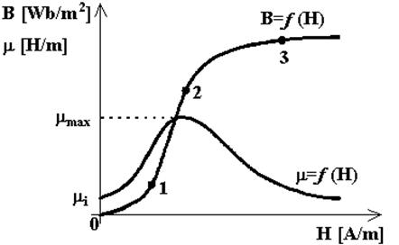
Fig. 8. Curve of first magnetization for a ferromagnetic
material
This curve can be described in
four parts:
1) 0-1 is typical for small
magnetizing fields and it is called “Rayleigh zone”. The permeability increases
by initial value ![]() and due to Rayleigh we
have a formulas which describes a linear behaviour [4]:
and due to Rayleigh we
have a formulas which describes a linear behaviour [4]:
![]() . (3.1)
. (3.1)
In this formula ![]() is the Ryaleigh
constant (
is the Ryaleigh
constant (![]() ) and for material of these rods its value is 350.000 [4].
For most materials permeability curve is in 0-1 a straight line when
) and for material of these rods its value is 350.000 [4].
For most materials permeability curve is in 0-1 a straight line when ![]() .
.
2) 1-2 part is characterized
by ![]() corresponding to knee
in the curve of first magnetization of material and by large
corresponding to knee
in the curve of first magnetization of material and by large ![]() (
(![]() ). This area is called “Barkhausen zone” and here
domains are instable and change very fast their orientation to rotate in the
direction of magnetic field maximum component. This variation is discontinued.
On this part we use linear low
). This area is called “Barkhausen zone” and here
domains are instable and change very fast their orientation to rotate in the
direction of magnetic field maximum component. This variation is discontinued.
On this part we use linear low
![]() (3.2)
(3.2)
where parameters ![]() and
and ![]() are defined through
the values of
are defined through
the values of ![]() ,
, ![]() and
and ![]() is an external field
when magnetization
is an external field
when magnetization ![]() has maximum
has maximum ![]() .
.
3) 2-3 is the part where the
magnetizing field increases and ![]() decreases; here there
is a smaller slope and
decreases; here there
is a smaller slope and ![]() . This part of curve is described by following relation for
. This part of curve is described by following relation for ![]() [4] known as
Frolich-Kennelly relation:
[4] known as
Frolich-Kennelly relation:
 (3.3)
(3.3)
where for material ![]() (this parameter
depends on initial permeability) and
(this parameter
depends on initial permeability) and ![]() which corresponds to
which corresponds to ![]() . For rod-1
. For rod-1 ![]() it means
it means ![]() and
and ![]() . This relation is very useful because shows a linear
relation between permeability (
. This relation is very useful because shows a linear
relation between permeability (![]() ) and field
) and field ![]() . In [4] it is available also the following empirical
relation (by Kennelly) which should be used for highest fields:
. In [4] it is available also the following empirical
relation (by Kennelly) which should be used for highest fields:
 . (3.4)
This relation can
be used to determinate ![]() .
.
4) saturation, in
this part induction ![]() is about constant and
is about constant and ![]() it is inclined to
value of the initial magnetic permeability.
it is inclined to
value of the initial magnetic permeability.
All empirical relations given imply that curve relating μ approach
saturation linearly.
When we place a rod inside of the solenoid the consequence of the
permeability is to introduce in this solenoid some currents whose effect is
similar to the effect of a current with intensity ![]() which flows into
which flows into ![]() coils along the
solenoid. There is the following relation for this current [5]:
coils along the
solenoid. There is the following relation for this current [5]:
![]() (3.5)
(3.5)
where ![]() is the number of coils
for unity of length of the solenoid (
is the number of coils
for unity of length of the solenoid (![]() ) and
) and ![]() is the relative
permeability of material. We assume that
is the relative
permeability of material. We assume that ![]() then the current is
then the current is
![]() (3.6)
(3.6)
and it is called
magnetizing current. This current can be considered as a current which flows in
perpendicular coils to the direction of field in the solenoid; it produces a
magnetic moment for unity of length of the solenoid:
![]() . (3.7)
. (3.7)
Volume of material
which presents this moment is ![]() (
(![]() is the unity of length of the solenoid). Magnetic moment for
unity of volume is
is the unity of length of the solenoid). Magnetic moment for
unity of volume is
![]() . (3.8)
. (3.8)
It is called
magnetization vector. This vector allows us to write function ![]() in the form
in the form
![]() (3.9)
(3.9)
5. EFFECT OF
THE FIELD OF A PERMANENT MAGNET ON HYSTERESIS RODS: THEORETICAL ANALYSIS
Consider configuration permanent magnet–hysteresis rod. We suppose
magnet has axis of symmetry and its moment is align this axis. Permanent magnet
field influences on the rod and there is possible displacement of working point
of rod and loses in effectiveness of rod’s work. If we want to reduce this effect we have to place rod
in an equatorial plane of magnet (passes through geometrical centre of magnet
and perpendicular its axis of symmetry) or in parallel plane.
We want to get
formula for ![]() component of vector
component of vector ![]() permanent magnet field
intensity along the rod. Next symbols are used (Fig. 9)
permanent magnet field
intensity along the rod. Next symbols are used (Fig. 9)
![]() – centre of magnet;
– centre of magnet;
![]() – point of rod in
which we analyse field component;
– point of rod in
which we analyse field component;
![]() (
(![]() )– perpendicular to rod’s projection on the equatorial plane
of magnet;
)– perpendicular to rod’s projection on the equatorial plane
of magnet;
![]() (
(![]() ) – distance between rod and equatorial plane of permanent
magnet;
) – distance between rod and equatorial plane of permanent
magnet;
![]() – distance SP.
– distance SP.
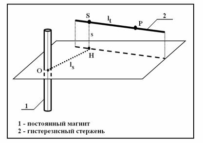
Fig. 9. Placement of
hysteresis rod and permanent magnet (1 – permanent magnet, 2 – hysteresis rod)
It is important to
say that field component has different signs on the right and left sides from
S. We use conception ferromagnetic materials consists of microscopic domains,
magnetic domains. Magnetic field are calculated with known formula
![]() (4.1)
(4.1)
where ![]() is radius-vector of
concerned point
is radius-vector of
concerned point ![]() from center of magnet
from center of magnet ![]() . Magnitude of magnetic field component alogn rod is
. Magnitude of magnetic field component alogn rod is
 . (4.2)
Consider a
situation then hysteresis rod is in permanent field of magnet and in variable
field. Due to field of magnet working point of rod displacements and
magnetization is not relative to zero field intensity but relative desplaced
value. To calculate the losess of rod work effectiveness we consider
parallelogram model of hysteresis. We have two cases.
·
Magnetization
without displacement (without permanent field) goes on main hysteresis loop to
average field intensity. Displacement of working point lead to magnetization
goes on a loop which area is equal to area of initial loop and, therefore, in
this case there is no losses of effectivness. (Fig. 10).
·
Working
point displacement leads to losses of effectivness in hysteresis rod work. Loop
area decreases (Fig. 11).

Fig. 10. Working point dicplacement without losses of
effectivness
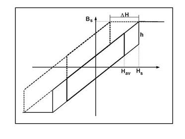
Fig. 11. Working point
displacement leads to losses of effectivness
To calculate losess
we assume hysteresis loop is parallelogram and permanent field component along
rod is the same (it is correct if distance between permanent magnet and rod are
bigger than rod’s length) or we take some average value of field intensity as
working point dicplacement. In this case losess of effictivness depend of
relation between three values: satiration intensity ![]() , magnetization amplitude
, magnetization amplitude ![]() and working point
displacement
and working point
displacement ![]() . Let
. Let ![]() and
and ![]() . Effectivness of rod work is proportional to magnetization
loop area ant losess are
. Effectivness of rod work is proportional to magnetization
loop area ant losess are
 (4.3)
(4.3)
where ![]() and
and ![]() are initial and final
hysteresis loop areas correspondingly. Function
are initial and final
hysteresis loop areas correspondingly. Function ![]() is defined in area
is defined in area ![]() , we suppose magnetization amplitude more than 0, otherwise,
there is no sense to speak about losess. Function
, we suppose magnetization amplitude more than 0, otherwise,
there is no sense to speak about losess. Function ![]() possesses values (Fig.
12)
possesses values (Fig.
12)
 (4.4)
(4.4)
where ![]() and
and ![]() .
.
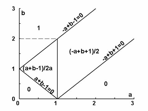
Fig. 12. Function of losses of
rod work effectovness under permanent magnet field
6.
EFFECT OF THE FIELD OF A PERMANENT MAGNET ON HYSTERESIS RODS: RESULTS OF THE
TESTS ON ROD-1
To avoid magnetization of the rods due to the presence of permanent
magnet on board of the satellite it is necessary to arrange the rods in the
equatorial plane of permanent magnet [6, 7]. Usually to reduce necessary time to stabilize the satellite
into orbit one increases number of the rods per axis but arrangement of
more parallel rods produce a mutual demagnetizing effect and requires to
arrange some of these rods in a plane which is not equatorial plane of the
permanent dipole. To evaluate demagnetizing effect (![]() ) of the rods in the design phase one needs simple
approximating relations. Different
approximating relations for rod demagnetization factor are summarized in [8].
An empirical optimal arrangement criteria for the rods is given in [2, 3]: rod
mutual demagnetizing effect can be neglected when the distance among the rods
is about 0.3∙l where l is the length of rod. In this section we
will discuss the results obtained in laboratory about the effect of a permanent
magnet on the hysteresis rods. To evaluate this effect different configurations
have been employed. Measurements have been carried out changing
inclination of the facility with respect to the Earth magnetic field as in the
previous measurements on the rods. Measurements have been obtained for a random
inclination (Series-I random
) of the rods in the design phase one needs simple
approximating relations. Different
approximating relations for rod demagnetization factor are summarized in [8].
An empirical optimal arrangement criteria for the rods is given in [2, 3]: rod
mutual demagnetizing effect can be neglected when the distance among the rods
is about 0.3∙l where l is the length of rod. In this section we
will discuss the results obtained in laboratory about the effect of a permanent
magnet on the hysteresis rods. To evaluate this effect different configurations
have been employed. Measurements have been carried out changing
inclination of the facility with respect to the Earth magnetic field as in the
previous measurements on the rods. Measurements have been obtained for a random
inclination (Series-I random ![]() ), in the perpendicular direction of coil-1 with respect to
the Earth magnetic field direction (Series-II normal
), in the perpendicular direction of coil-1 with respect to
the Earth magnetic field direction (Series-II normal ![]() ) and in the same direction of the Earth magnetic field
(Series-III parallel
) and in the same direction of the Earth magnetic field
(Series-III parallel ![]() ). In each of these positions tests have been iterated
for different values of voltage applied to the solenoid and changing position
of the permanent magnetic with respect to the rod: when permanent magnet is
centred with respect to the coil-2 (Fig. 13a), when permanent dipole is located
in an advanced position (in the left side) with respect to the coil-2 (Fig.13b)
and in the last when permanent magnet is located at right side with respect to
the position of the coil-2 during measurements (Fig. 13c).
). In each of these positions tests have been iterated
for different values of voltage applied to the solenoid and changing position
of the permanent magnetic with respect to the rod: when permanent magnet is
centred with respect to the coil-2 (Fig. 13a), when permanent dipole is located
in an advanced position (in the left side) with respect to the coil-2 (Fig.13b)
and in the last when permanent magnet is located at right side with respect to
the position of the coil-2 during measurements (Fig. 13c).
Permanent magnet used for testing is the same one arranged on board of
the TNS-0 nanosatellite successfully launched in orbit from the International
space station (ISS) in March 2005. TNS-0 nanosatellite weights about 4.5 kg and
its structure is constituted by a cylinder with a diameter of 170 mm and a
length of 250 mm [9]. Value of the moment of the permanent magnet is 2.2
A∙m2.
Measurements have been repeated for different distances between
permanent dipole and rod. A board to summarize all these configurations is
given in Table 3. Sizes of permanent dipole used for testing and configuration
for measurements are available in Fig. 14.
Table
3. Main parameters used to change configuration during tests on the hysteresis
rods to evaluate the effect of permanent magnet: Vcoil (voltage applied to
coil-1), distance between rod and magnet and direction of the facility with
respect to the Earth magnetic field
|
Vcoil
(V) |
Distance-ls
(cm) |
Direction |
|
0.5 |
ls
1=1.6 cm |
Perpendicular
to BE |
|
1 |
ls
2=3 cm |
Parallel
to BE |
|
2 |
ls
3= 4.5 cm |
Random
inclination with respect to BE |
Fig. 13. Different positions for the permanent magnet
with respect to the rod
Fig. 14. Configuration for the measurements carried out
to evaluate effect of a permanent dipole on the hysteresis rods
Results of
measurements carried out on the rod-1 when ![]() in the direction of
the facility perpendicular to the Earth magnetic field for the configuration of
Fig. 13.a are available in Fig. 15. Measurements have been carried out with
facility in the direction perpendicular to the geomagnetic field. In the
diagram we see that when
in the direction of
the facility perpendicular to the Earth magnetic field for the configuration of
Fig. 13.a are available in Fig. 15. Measurements have been carried out with
facility in the direction perpendicular to the geomagnetic field. In the
diagram we see that when ![]() the signal measured
with coil-2 is pressed at about 20 mV along all rod. Increasing the distance
between dipole and the rod arranged inside the coil-1 effect of dipole
decreases as expected. In Fig. 16 and Fig. 17 results carried out when
the signal measured
with coil-2 is pressed at about 20 mV along all rod. Increasing the distance
between dipole and the rod arranged inside the coil-1 effect of dipole
decreases as expected. In Fig. 16 and Fig. 17 results carried out when ![]() and
and ![]() respectively in the
direction of the facility perpendicular to the Earth magnetic field with
permanent magnet centered with respect to coil-2 are sketched.
respectively in the
direction of the facility perpendicular to the Earth magnetic field with
permanent magnet centered with respect to coil-2 are sketched.
Fig. 15. Permanent dipole located in the middle of coil-2
for different distances between dipole and rod: ls=1,6 cm, ls=3 cm and ls=4.5
cm. Results of the measurements for rod-1, Vcoil=0.5 V
In the Fig. 16 some peaks are visible in the measurements along the rod.
Probably this behaviour depends by unintentionally mechanical stress suffered
by the rod during different set of measurements when we pushed and extracted
rod in the solenoid different times.
Fig. 16. Permanent dipole located in the middle of coil-2
for different distances between dipole and rod: ls=1,6 cm, ls=3 cm and ls=4.5
cm. Results of the measurements for rod-1, Vcoil=1 V
Fig. 17. Permanent dipole located in the middle of coil-2
for different distances between dipole and rod: ls=1,6 cm, ls=3 cm and ls=4.5
cm. Results of the measurements for rod-1, Vcoil=2 V
Comparison among these results shows that in the direction perpendicular
to the geomagnetic field when ![]() is about 4.5-5 cm
effect of permanent magnet can be neglected. Measurements have been replied in
the direction parallel to the geomagnetic field changing the value of
is about 4.5-5 cm
effect of permanent magnet can be neglected. Measurements have been replied in
the direction parallel to the geomagnetic field changing the value of ![]() : results show that in this case to neglect the effect of
permanent dipole on the hysteresis rod it is necessary a bigger distance with
respect to the previous case about
: results show that in this case to neglect the effect of
permanent dipole on the hysteresis rod it is necessary a bigger distance with
respect to the previous case about ![]() . Tests replied with the facility in a random inclination
with respect to the Earth magnetic field confirm this result. In a general
direction to neglect the effect of permanent dipole on the rod-1, the dipole
has to be located at least 6.5 cm far from the rod. Results of the measurements
carried out on the rod-1 when
. Tests replied with the facility in a random inclination
with respect to the Earth magnetic field confirm this result. In a general
direction to neglect the effect of permanent dipole on the rod-1, the dipole
has to be located at least 6.5 cm far from the rod. Results of the measurements
carried out on the rod-1 when ![]() in the direction of
the facility parallel to the Earth magnetic field for the configuration of Fig.
13 (a) are available in Fig. 18.
in the direction of
the facility parallel to the Earth magnetic field for the configuration of Fig.
13 (a) are available in Fig. 18.

Fig. 18. Permanent dipole located in the middle of coil-2
for different distances between dipole and rod: ls=1,6 cm, ls=3 cm and ls=4.5
cm. Results of the measurements for rod-1, Vcoil=1 V
For easy comparison among results obtained in the different
configurations experimental measurements performed for rod-1 when ![]() with the facility
located in a random direction with respect to the Earth magnetic field,
considering the configuration with the dipole centred with respect to the
coil-2 are shown in Fig. 19.
with the facility
located in a random direction with respect to the Earth magnetic field,
considering the configuration with the dipole centred with respect to the
coil-2 are shown in Fig. 19.
Fig. 19. Permanent dipole located in the middle of coil-2
for different distances between dipole and rod: ls=1,6 cm, ls=3 cm and ls=4.5
cm. Results of the measurements for rod-1, Vcoil=2 V
At this point we
carried out a series of measurements to evaluate effect of dipole when its
position changes with respect to the rod and coil-2. In Fig. 20 one can see
that shape of the signal changes with a translation of peak of the signal
versus left. If we rotate the dipole changing the versus of its magnetic moment
it is important to notice a different effect on the signal of the rod (Fig.
21).
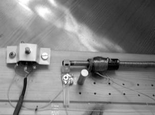
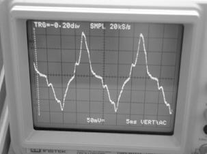
Fig. 20. Effect of the position of dipole with respect to
the rod: the shape of signal changes with a translation of peak of the signal
vs left
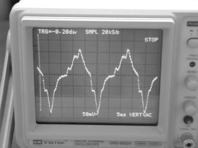
Fig. 21. Changing of the signal generated by rod when
dipole is rotated to obtain an opposite versus for its magnetic moment
Comparison of the measurements obtained changing position of dipole when
voltage applied to the coil-1 is ![]() with the facility
arranged in the perpendicular direction to the geomagnetic field and with the
dipole located at 3 cm far from rod are available in Fig. 22. When
with the facility
arranged in the perpendicular direction to the geomagnetic field and with the
dipole located at 3 cm far from rod are available in Fig. 22. When ![]() in this configuration
effect of the dipole can be neglected. Measurements carried out for
in this configuration
effect of the dipole can be neglected. Measurements carried out for ![]() and
and![]() confirm results shown in Fig. 22: effect of dipole does not
change in a very significant way when its position changes from the centre to
the left side or right side at the same distance from rod.
confirm results shown in Fig. 22: effect of dipole does not
change in a very significant way when its position changes from the centre to
the left side or right side at the same distance from rod.
Fig. 22. Permanent dipole located at ls=3 cm in different
positions with respect to the rod and coil-2. Results of the measurements for
rod-1, Vcoil=1 V
Results obtained when
facility is located in a general direction with respect to the magnetic field
of the Earth with the dipole located at 3 cm far from rod confirm this result
(Fig. 23). Results obtained in the parallel direction of the facility with
respect to the magnetic field of the Earth seem to contradict this result (Fig.
24): to interpret and to confirm these results it is necessary to repeat a
series of measurements in the parallel direction with respect to the
geomagnetic field for this rod. Results and comparison with behaviour of the
rod-2 can be useful to analyze these results: effect of a permanent magnet on
the rod-2 is the topic of the next section.

Fig. 23. Permanent dipole located at ls=3 cm in different
positions with respect to the rod and coil-2. Results of the measurements for
rod-1, when Vcoil=2 V
Fig. 24. Permanent dipole located at ls=3 cm in different
positions with respect to the rod and coil-2. Results of the
measurements for rod-1, Vcoil=1 V
7. EFFECT OF
THE FIELD OF A PERMANENT MAGNET ON HYSTERESIS RODS: RESULTS OF THE TESTS ON
ROD-2
Measurements have been carried out on the rod-2 following the scheme
available in Table 3: changing distance of permanent dipole with respect to the
rod-2 for different voltage applied to the coil-1 in different positions of the
permanent magnet with respect to the direction of the geomagnetic field and
changing location of the dipole with respect to the coil-2. Results obtained
for rod-2 show that effect of permanent magnet is smaller then for rod-1: when
the distance of the permanent dipole with respect to the rod-2 is about 3 cm
effect of field of the magnet can be neglected (Fig. 25).
Fig. 25. Permanent dipole located in the middle of coil-2
for different distances between dipole and rod: ls=1,6 cm, ls=3 cm and ls=4.5
cm. Results of the measurements for rod-2, when Vcoil=0.5 V
These results have
been confirmed for different voltages applied in different positions of the
facility with respect to the geomagnetic field as we see in Fig. 26 where
results for ![]() in the perpendicular
direction of the facility with respect to the geomagnetic field are shown.
in the perpendicular
direction of the facility with respect to the geomagnetic field are shown.
Fig. 26. Permanent dipole located in the middle of coil-2
for different distances between dipole and rod: ls=1,6 cm, ls=3 cm. Results of
the measurements for rod-2, Vcoil=1 V
Comparison of the results shown in Fig. 26 for rod-2 with results shown
in Fig.16 obtained for rod-1 gives a very different effect of a permanent
magnet on two rods used for testing in the laboratory. Same comparison can be
done for Fig. 18 and Fig. 27 where results for ![]() in the parallel
direction of the facility with respect to the geomagnetic field for rod-1 and
rod-2 respectively are shown. In the last also in this case effect of changing
of position of the permanent dipole with respect to the coil-2 during the
measurements has been evaluated: results for rod-2 when voltage applied to the
coil-1 is
in the parallel
direction of the facility with respect to the geomagnetic field for rod-1 and
rod-2 respectively are shown. In the last also in this case effect of changing
of position of the permanent dipole with respect to the coil-2 during the
measurements has been evaluated: results for rod-2 when voltage applied to the
coil-1 is ![]() with the facility
arranged in the perpendicular direction to the geomagnetic field and with the
dipole located at 1.6 cm far from the rod are available in Fig. 28. Comparison
with diagram of Fig. 22 obtained for rod-1 in the same conditions shows that
effect of a changing of the position of the permanent magnet is different and
bigger for rod-2.
with the facility
arranged in the perpendicular direction to the geomagnetic field and with the
dipole located at 1.6 cm far from the rod are available in Fig. 28. Comparison
with diagram of Fig. 22 obtained for rod-1 in the same conditions shows that
effect of a changing of the position of the permanent magnet is different and
bigger for rod-2.
Fig. 27. Permanent dipole located in the middle of coil-2
for different distances between dipole and rod: ls=1,6 cm, ls=3 cm. Results of
the measurements for rod-2,Vcoil=1 V
Fig. 28. Permanent dipole located at ls=1.6 cm in
different positions with respect to the rod and coil-2. Results of the
measurements for rod-2, Vcoil=1 V
These results have
been confirmed for different voltages applied to the coil-1 and in different
positions of the facility with respect to the direction of geomagnetic field:
in Fig. 29 and Fig. 30 some results of the measurements for rod-2 are sketched
to allow easy comparison with results of the measurements obtained for the
rod-1 available in Fig. 23 and Fig. 24. These results show that effect of a
magnet dipole can be very different depending from rod and from its properties.
In any case these preliminary tests demonstrated that with this simple facility
it is possible to establish the minimum distance necessary to arrange a
permanent dipole and a set of rods on board of a small satellite to avoid
mutual interferences. This is a very useful result when designers need to
choice the arrangement of the dipole and of the rods on board of the satellite
in the preliminary phase of design and integration of all subsystems.
Fig. 29. Permanent dipole located at ls=1.6 cm in
different positions with respect to the rod and coil-2. Results of the
measurements for rod-1, Vcoil=2 V
Fig. 30. Permanent dipole located at ls=1.6 cm in
different positions with respect to the rod and coil-2. Results of the
measurements for rod-2, Vcoil=1 V
8. CONCLUSIONS AND NEXT DEVELOPMENT
The paper presents results of the continuation of the experimental
activity described in [1]. In [1] the results of preliminary tests carried out
on two different hysteresis rods using a facility opportunely sized and
developed have been presented. In particular, tests have been performed to
evaluate effect of a permanent magnet on the hysteresis rods when they are
arranged in a plane different by equatorial plane of the permanent magnet.
Preliminary results showed that this effect depend strongly by the rod and they
confirmed that it is possible to employ the developed facility to evaluate in a
simple and fast way the minimum necessary distance between permanent dipole and
rods to avoid interferences which reduce the rod efficiency on board of a
satellite. Next steps are necessary in this experimental activity. It is
important to repeat tests on other hysteresis rods for a better and more
accurate analysis of the signal obtained in the oscilloscope when voltage
applied to the solenoid changes and to confirm behaviour of this signal along
the rod. To evaluate effect of a permanent dipole on the hysteresis rods it is
necessary to repeat tests in different configurations especially in different
planes with respect to the equatorial plane of the permanent magnet because in
this preliminary work the position of the rod was fixed. It would be also
useful to confirm experimentally that effect of magnet can be neglected when
rod is arranged in the equatorial plane of the permanent dipole as it can be
demonstrated theoretically. It is useful to use this facility to investigate
mutual demagnetizing effect which appears when more parallel rods are arranged
on board of the satellite, in order to confirm important experimental result
available in [3] which fixes at 0.3 l the minimum necessary distance between
two rods to neglect the mutual demagnetization effect using different kind of
rods. Another basic goal of the research is to analyze all experimental results
in order to try to develop a general modelling of the magnetic permeability of
the rod depending by its length. In this direction a first step has been
performed describing analytically the magnetic permeability curve when the
applied magnetizing field changes.
9. AKNOWLEDGEMENTS
The
work was supported by the Russian Foundation for Basic Research (Grants N
06-01-00389 and N 07-01-92001), the Program of the Leading Scientific Schools
Support (Grant N NSh-2448.2006.1) and Italian Space Agency.
REFERENCES
[1]
M.L.Battagliere, F.Graziani, N.V.Kupriyanova, M.Yu.Ovchinnikov, V.I.Pen’kov, Design, building and
experimental results of a facility to test hysteresis rod parameters, Preprint of Keldysh Institute of Applied Mathematics Russian Academy of
Sciences, Moscow, 2007, № , 27p.
[2]
M.Yu.Ovchinnikov and V.I.Penkov, Passive
Magnetic Attitude Control System for the Munin Nanosatellite, Cosmic Research,
Vol.40, No. 2, 2002, pp 142-156
[3] A.P.Kovalenko, Magnetic Attitude Control Systems of Space
Vehicles, M., Mechanical Engineering, 1975, 248p.
[4] R.M.Bozort, Ferromagnetism, Van Nostrand Company, Reinhold, New York 1951
[5] D.Sette, M.Bertolotti, Lezioni di Fisica 2: Elettromagnetismo e
ottica, Masson 1998, Milano
[6] M.Yu.Ovchinnikov and V.I.Penkov, Passive Magnetic Attitude Control System for
the Munin Nanosatellite, Cosmic Research, Vol.40, No. 2, 2002, pp 142-156
[7] M.Zelli, Stabilizzazione
magnetica di microsatelliti, Degree Thesis at School of Aerospace
Engineering of University of Rome La Sapienza (Supervisor Prof. F. Graziani,
co-supervisor Prof. F. Santoni), July 2004
[8] F.Santoni and M.Zelli, Passive magnetic attitude stabilization of
the Unisat-4 microsatellite, Paper IAC-06-C1.1.5 at the 57th Congress IAF,
Valencia, Spain, 2-6th October 2006, 7p.
[9] Yu.M.Urlichich, A.S.Selivanov, A.A.Stepanov, Two nanosatellites for space experiments, Extended Abstracts of the 5th IAA Symposium on
Small Satellites for Earth Observation, April 4-8, 2005, Berlin, Germany, Paper
IAA-B5-1403, 3p.
APPENDIX
1:LIST OF SYMBOLS
![]() voltage
voltage
![]() voltage peak
(maximum amplitude)
voltage peak
(maximum amplitude)
![]() voltage peak to
peak
voltage peak to
peak
![]() current
current
![]() elongation of rod
elongation of rod
![]() magnetic dipole
intensity
magnetic dipole
intensity
![]() magnetic field
induction vector
magnetic field
induction vector
![]() magnetic field
induction
magnetic field
induction
![]() magnetic field
intensity vector
magnetic field
intensity vector
![]() magnetic field
intensity
magnetic field
intensity
![]() magnetization
vector
magnetization
vector
![]() magnetic flux
magnetic flux
![]() currant in coil
currant in coil
![]() voltage in coil
voltage in coil
![]() coil magnetic field
induction
coil magnetic field
induction
![]() coil magnetic field
intensity
coil magnetic field
intensity
![]() magnetic field
induction of saturation
magnetic field
induction of saturation
![]() retentivity
retentivity
![]() geomagnetic field
induction
geomagnetic field
induction
![]() intensity of
saturation
intensity of
saturation
![]() coercitive force
coercitive force
![]() geomagnetic field intensity
geomagnetic field intensity
![]() magnetic permeability
of vacuum
magnetic permeability
of vacuum
![]() initial magnetic
permeability
initial magnetic
permeability
![]() maximum magnetic
permeability
maximum magnetic
permeability
![]() relative
permeability of material
relative
permeability of material
![]() initial magnetic
permeability of rod
initial magnetic
permeability of rod
![]() maximum magnetic
permeability of rod
maximum magnetic
permeability of rod
![]() Ryaleigh constant
Ryaleigh constant